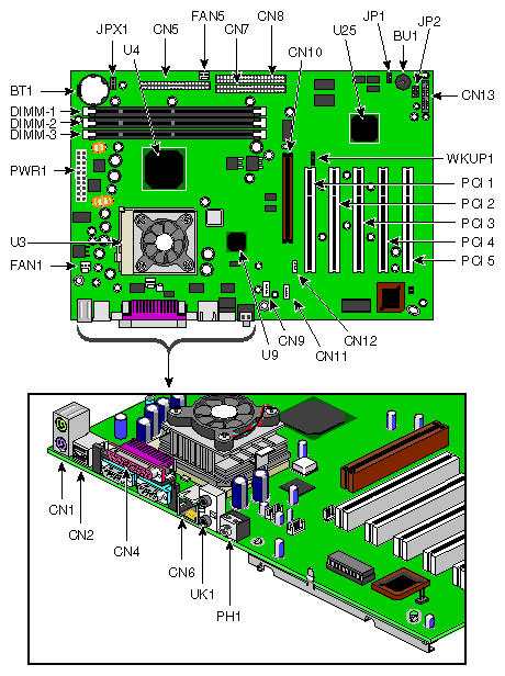
The Silicon Graphics 230 Visual Workstation contains an M23D system board. This chapter describes the M23D system board and all its major components. It contains the system board layout, jumper settings, cache and memory configurations, and information on other internal devices.
The M23D system board is a PCI bus-based, single processor system board built on an extended ATX baseboard. It comes with a single FC-PGA (Flip-Chip Pin Grid Array) processor socket using a Pentium® III processor integrated with the VIA Apollo Pro 133A chipset. The system board also integrates the Intel® 82559 10/100 Mbps PCI Ethernet chipset that supports WOL (Wake on LAN) and AOL (Alert on LAN) for better remote site management.
For expandability, the system board includes one AGP (Accelerated Graphics Port) slot, five PCI-bus slots, and three DIMM sockets.
For connectivity, the system board supports two USB (Universal Serial Bus) connectors, a speaker-out/audio-out, audio-in, and microphone-in port, and other standard features such as two UART NS16C550 serial ports, one enhanced parallel port with Enhanced Parallel Port (EPP)/Extended Capabilities Port (ECP) support, a diskette drive interface, and two embedded hard disk interfaces.
The Pentium III processor implements Dynamic Execution performance, a multi-transaction system bus, and Intel MMX media enhancement technology. Also, it offers Streaming SIMD (Single Instruction Multiple Data) Extensions — 70 new instructions enabling advanced imaging, 3D, streaming audio and video, and speech recognition applications. The Pentium III processor delivers higher performance than the previous Pentium processor while maintaining binary compatibility with all previous Intel architecture processors.
The three DIMM sockets on the board allow a maximum of 1.5 GB of memory using three 512-MB SDRAM (Synchronous DRAM) DIMMs. For data integrity, the default setting of the ECC (Error-Correcting Code) function of the memory system in the BIOS is enabled.
 | Note: Only 3.3 volts SDRAM should be used; 5-volt memory devices are not supported. |
The VIA Apollo Pro 133A chipset was specifically designed to meet the needs of high performance systems. It consists of two components: VT82C694X (north bridge) and VT82C686A (south bridge).
VT82C694X (north bridge) provides the host interface, memory system control interface, PCI interface, and AGP interface to boost graphics performance.
VT82C686A (south bridge) integrates super I/O functions like keyboard and mouse interface, floppy disk controller, advance digital data separator, two compatible serial ports (UARTs), one parallel port, on-chip 12 mA AT bus drivers, one floppy direct drive support, and Intelligent Power Management support. It also supports the PC99 compliant PCI-to-ISA bridge, SoundBlaster/DirectSound AC97 audio, SMBus and others.
Another cost-effective feature for network solution is the integration of Intel's 82559 10/100 Mbps Fast Ethernet controller which supports Advanced Configuration and Power Interface (ACPI) 1.20A based power management, Wired for Management (WfM) 2.0 compliance, IP checksum assist, PCI 2.2 compliance, and PC 99 compliance.
AGP is developed solely for the purpose of supporting 3D graphic applications. It has a 32-bit wide channel that runs at 66 MHz, which translates into a total bandwidth of 266 MBps. This is twice the bandwidth of PCI buses (133 MBps). AGP also accesses the main memory directly, allowing 3D textures to be stored in main memory rather than video memory.
The system board supports the power-management function that conforms to the power-saving standards of the U.S. Environmental Protection Agency (EPA) Energy Star program. It also offers the Plug-and-Play feature. This feature saves the user from configuration troubles, thus making the system more user-friendly.
The system board has the following major components:
Utilizes a FC-PGA (Flip-Chip Pin Grid Array) processor socket that supports a Pentium III processor and future generations of Pentium CPUs
VIA Apollo Pro 133A chipset which includes the north and the south bridge
Onboard 10/100 Mb/s Intel 82559 LAN chip that supports WOL and AOL
Three DIMM sockets that accept 64-, 128-, 256-, and 512-MB SDRAMs with a maximum memory capacity of 1.5 GB
One AGP bus and five PCI bus slots
System clock/calendar with battery backup
IDE hard disk and diskette drive interfaces
External ports:
USB connectors
PS/2-compatible keyboard port
PS/2-compatible mouse port
10/100 MBps Ethernet port
Parallel port
Serial port 1 and 2
Speaker-out/Audio-out port
Audio-in port
Microphone-in port
This section provides a description of the system board connectors. Figure 3-1 shows the location of connectors on the system board.
Table 3-1 provides a description of the system board connectors.
Table 3-1. Connector descriptions
No. | Description |
|---|---|
BT1 | Battery |
BU1 | Buzzer |
CN1 | Above: PS/2 mouse port |
CN2 | USB ports |
CN3 | CPU thermal sensor (reserved) |
CN4 | Above: Parallel port |
CN5 | Floppy disk drive connector |
CN6 | LAN port |
CN7 | IDE 1 connector |
CN8 | IDE 2 connector |
CN9 | Fax voice connector (reserved) |
CN10 | AGP slot |
CN11 | CD Audio-in connector |
CN12 | Wake on LAN connector |
CN13 | Multi connector (see Table 3-2 for multi connector description) |
DIMM1-3 | DIMM slots |
Fan1 | Rear housing fan connector |
Fan2 | CPU fan connector |
Fan5 | Front housing fan connector |
JP1 | BIOS setting |
JP2 | On board buzzer/external speaker select |
JPX1 | Frequency setting ) |
PWR1 | ATX power supply connector |
PCI 1-5 | PCI slots |
PH1 | Mic-in port |
U3 | CPU socket |
U4 | VIA Apollo Pro 133A chipset (north bridge) |
U9 | Intel 82559 LAN chipset |
U25 | VIA Apollo Pro 133A chipset (south bridge) |
UK1 | Above: Audio-in port |
WKUP1 | Wake on Ring connector |
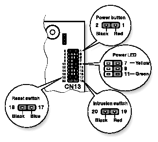
Table 3-2 details the functions of the CN13 connector settings.
Table 3-2. Multi Connector details
Setting | Function |
|---|---|
1-2 | Power button connector |
7-9-11 | Power LED connector |
8-10-12-14 | HDD LED connector |
17-18 | Reset switch connector |
19-20 | Intrusion switch connector |
Figure 3-2 illustrates the CN13 connector settings.
Table 3-3 provides the frequency settings for the JPX1 jumper. JPX1 sets the ratio between the front side bus (FSB) frequency and the CPU internal clock frequency. This information is only required if installing a CPU other than the one supplied by SGI.
1 | 2 | 3 | 4 | Frequency |
|---|---|---|---|---|
On | On | On | On | 2 |
On | On | Off | On | 2.5 |
On | Off | On | On | 3 |
On | Off | Off | On | 3.5 |
Off | On | On | On | 4 |
Off | On | Off | On | 4.5 |
Off | Off | On | On | 5 |
Off | Off | Off | On | 5.5 |
On | On | On | Off | 6 |
 | Note: This frequency setting table is for reference only and is reserved for use by customer service technicians. The CPU frequency is automatically set and should not be tampered with. |
The following sections show you how to install system components. This includes the CPU, memory modules, and expansion cards.
Follow electrostatic discharge (ESD) precautions. Electronic equipment can be irreparably damaged by ESD. Always follow these preventative measures when handling a system component:
Remove a component from its antistatic bag only when you are ready to install it.
If you have to handle a component before installation, do not place it on surfaces that produce ESD (carpeting, for example), or near devices that create static electricity.
Attach a static wrist strap to a grounded connection on your system when installing or removing a component.
The Pentium III comes in a FC-PGA (Flip-Chip Pin Grid Array) 370 pin package.
 | Caution: Always observe the ESD precautions when installing or removing a system component. Refer to the preceding section. |
Follow these steps to install a CPU:
Remove the processor from its protective packaging.
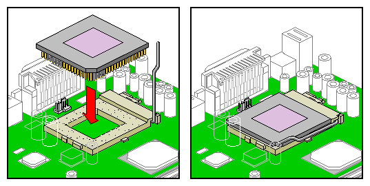
Insert the new CPU into the CPU socket. Make sure that pin 1 (indicated by a notched corner) of the CPU connects to hole 1 of the socket. Push down the socket lever to lock the new CPU into the socket, as shown in Figure 3-3.
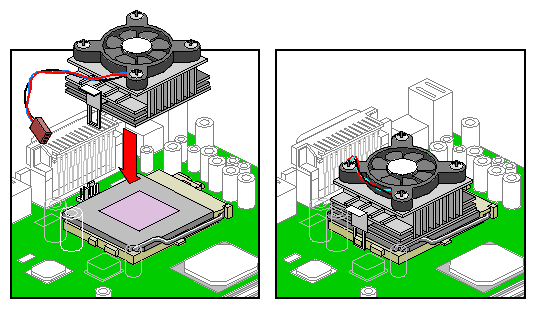
Connect the 3-pin and 2-pin fan/heatsink cables to the system board. Refer to “System Board Layout” for the location of the fan/heatsink connectors.
Attach one side of the fan/heatsink metal bracket to the CPU socket and then gently push down the other side of the metal bracket until it locks in place. Figure 3-4 illustrates the procedure.

Caution: The heatsink becomes very hot when the system is on. NEVER touch the heatsink with any metal or with your hands.
The three 168-pin sockets onboard support SDRAM-type DIMMs. You may install 64-MB, 128-MB, 256-MB, or 512-MB (single and double density) DIMMs for a maximum 1.5-GB system memory.
 | Note: Only 3.3 volts SDRAM should be used; 5-volt memory devices are not supported. |
This system board supports 133 MHz ECC registered SDRAM only.
 | Warning: Do not use both 100 MHz and 133 MHz SDRAM together. This might cause your system to malfunction. For a qualified DIMM vendor list, please call for support. |
Each of the DIMM sockets is independent from the others. This independence allows you to install DIMMs with different capacities to form different memory configurations.
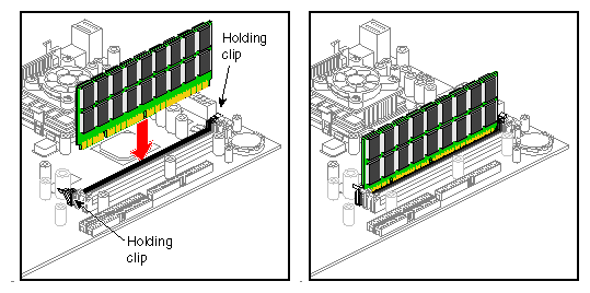
To install a DIMM, align it to an empty slot and press it in until the holding clips secure the DIMM in place, as shown in Figure 3-5.
 | Note: The DIMM socket is slotted to ensure proper installation. If you attempt to install a DIMM, but it does not completely fit, you may have inserted it the wrong way. Reverse the orientation of the DIMM. |
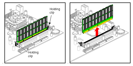
To remove a DIMM, press the holding clips on both sides of the socket outward to release the DIMM, as shown in Figure 3-6.
Do not continue using the computer if you receive an error message of any type. Note the message and take corrective action. This section explains the different types of error messages and corresponding corrective measures.
There are two general types of error messages:
Software error messages
System error messages
Software error messages are returned by your operating system or application. These messages typically occur after you boot the operating system or when you run your applications. If you receive this type of message, consult your application or operating system manual for help.
A system error message indicates a problem with the computer itself. A message of this type normally appears during the power-on self-test, before the operating system prompt appears. Table 3-4 lists some of the system error messages and the corrective action to take.
Table 3-4. System Error Messages
Message | Action |
|---|---|
CMOS Battery Bad | Replace the lithium battery or call for support. |
CMOS Checksum Error | Run Setupa. |
CPU BIOS Update Code Mismatch | Call for support. |
Diskette Drive Controller Error or Not Installed Floppy Disk Controller Error | Check and connect the floppy cable on both the floppy drive and system board end. |
Diskette Drive Error | Check the CMOS settings in Setupa and the floppy drive cable connections. |
Diskette Drive A Type Mismatch Floppy Drive A Error | Run Setupa and select the proper floppy drive type. |
Diskette Drive B Type Mismatch Floppy Drive B Error | Run Setupa and select the proper floppy drive type. |
Equipment Configuration Error | Modify memory configuration. Call for support. |
Expansion ROM Allocation Failed | Call for support. |
Hard Disk Controller Error | Run Setupa or check the hard disk cable connection. |
Hard Disk 0 Error IDE Primary Channel Master Drive Error | Check all cable connections. Replace hard disk. |
IDE Primary Channel Slave Drive Error | Check all cable connections. Replace hard disk. |
Hard Disk 1 Error IDE Secondary Channel Master Drive Error | Check all cable connections. Replace hard disk. |
IDE Secondary Channel Slave Drive Error | Check all cable connections. Replace hard disk. |
Hard Disk 0 Extended Type Error | Run Setupa. |
Hard Disk 1 Extended Type Error | Run Setupa. |
IRQ Setting Error | Run Setupa to make sure there is no IRQ device conflict. |
I/O Parity Error | Call for support. |
I/O Resource Conflict(s) | Check the serial port and parallel port to make sure there are no IRQ or I/O address conflict. |
I2C Interface or Device(s) Error, System Halt | Shut down and disconnect the power cable or call for support. |
PS/2 Keyboard Error or No Keyboard Connected | Check and connect the keyboard to the system unit. |
PS/2 Keyboard Interface Error | Replace the keyboard or call for support. |
PS/2 Pointing Device Error | Check and connect pointing device connection. |
PS/2 Pointing Device Interface Error | Run Setupa and check pointing device. |
Memory Error at: MMMM:SSSS:OOO (W:XXXX, R:YYYY)where:M: MB, S: Segment, O: Offset, X/Y: write/read pattern | Call for support. |
Memory Resource Conflict(s) | Call for support. |
Memory Size Mismatch CPU Clock Mismatch | Check the memory size based on the system specifications. Run Setupa. If the message reappears, ask for technical assistance. |
NVRAM Checksum Error | Call for support. |
Onboard Pointing Device Interface Error | Replace the pointing device or call for support. |
Real Time Clock Error | Run Setupa and set the time and date. |
RAM Parity Error | Call for support. |
64K System Management Memory Bad | Call for support. |
SMRAM Not Exist | Call for support. |
Press Esc to turn off NMI, any key to reboot | Press ESC to disregard the NMI error. Press any other key to reboot the system. If this happens repeatedly call for support. |
a. Press CTRL + ALT + ESC during power-on self-test (POST) to enter the BIOS Set-up screen. See Chapter 4, “Setup Utility” for information on running Setup.
As a general rule, if an error message says Press F1 to continue, it is caused by a configuration problem, which can be easily corrected. An equipment malfunction is more likely to cause a fatal error, i.e., an error that causes complete system failure.
Here are some corrective measures for error conditions:
Run Setup. You must know the correct configuration values for your system before you enter Setup, which is why you should write them down when the system is correctly configured. An incorrect configuration is a major cause of power-on error messages, especially for a new system.
Remove the system unit cover. Check that the jumpers on the system board and any expansion boards are set correctly.
If you cannot access a new disk, it may be because your disk is not properly formatted or partitioned. Please consult your operating system documentation for additional information.
Check that all connectors and boards are securely plugged in.
If you go through the corrective steps above and still receive an error message, the cause may be an equipment malfunction.
If you are sure that your configuration values are correct and your battery is in good condition, the problem may lie in a damaged or defective chip.
In either case, contact an authorized service center for assistance.
The BIOS Utility allows you to view your system's configuration settings.
When you receive the system, it will already have been configured by SGI. There is no need to run Setup when starting the computer unless you get a Run Setup message.
The Setup program loads configuration values into the battery-backed nonvolatile memory called CMOS RAM. This memory area is not part of the system RAM.
 | Note: If you repeatedly receive Run Setup messages, the battery may be bad. In this case, the system cannot retain configuration values in CMOS. Replace the battery or call for support. |
